-
Re-capping the Spectrum
Electrolytic caps degrade over time and after 30+ years those on the Spectrum PCB will be well out of spec. On the 16/48K models bad caps most noticeably affect the video quality, but can also cause other problems too (stability etc). Fortunately, replacing the caps is a pretty straightforward job – (I have packs available for all models at the store).
Info / Tips:
Capacitors come in various packages, but as far as the Spectrum goes they’ll either be axial types (which have a lead at each end of a cylindrical body) or radial types (both leads come from the same end). These days we’re not exactly spoilt for choice when it comes to axial capacitors, but it’s possible to replace axials with radials (in order to use known-brand types at lower cost) by bending one lead – the positive as it is usually the longest – over the body and laying the cap horizontally, with the exposed wire upwards.
The electrolytic capacitors in the Spectrum are polarized (meaning they have a negative and positive side) and must be fitted the same way around as the originals on the PCB. The negative lead of a capacitor is marked with a band of arrows. The positive lead (on axial caps) is nearest to the indentation in the body of the cap. There is usually a “+” symbol on the PCB showing the correct orientation (beware of the printing error at C46 on Issue 2 boards – see below.)
The voltage rating on modern caps is often higher than those originally used. This is not important as this figure only refers to the maximum voltage which can be safely applied – the Spectrum works well below these voltages. It is the capacitance (in μF) that is the important value.
Probably the easiest way to remove the old caps is to clip one lead near the body of the cap, bend the cap away from the board and pull on it as you hold the soldering iron tip on the other lead’s pad on the back of the board. The stub of the remaining lead can be pressed flush at the solder side of the board and then plucked out with tweezers from the component side (whilst holding the iron on the lead near the upper pad). To help things along, it’s worth adding fresh solder to both pads. The holes will be plugged with solder but this can be easily cleared with a solder sucker, braid and flux (or combination of all three) – again, adding extra solder usually helps.
The soldering iron used for re-capping does not have to anything special, but must be of a decent wattage and should not have too fine a tip as there are wide tracks that will draw a lot of heat from the iron. (An Antex XS25 or similar should be fine). Avoid lead-free solder as it can be a pain to use. Standard tin-lead 60/40 0.7mm with Rosin flux is perfect.
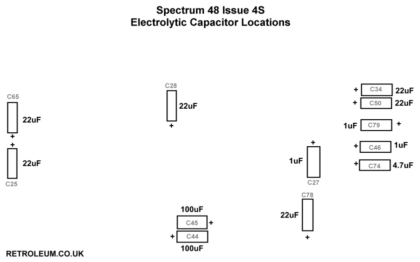
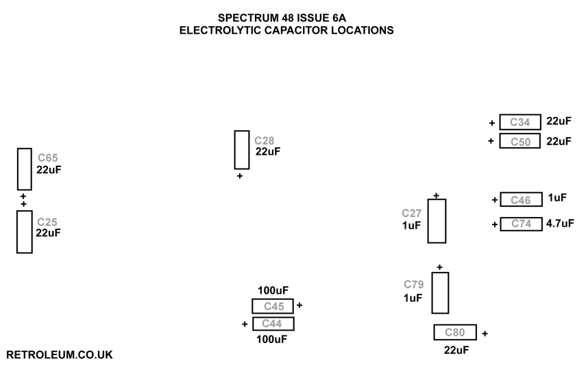
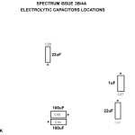
You may prefer to remove and replace a single capacitor at a time so that you don’t forget which value goes where. In case of problems, here are the locations of the caps on all Spectrum 16/48 boards (click to enlarge).
Issue 2
Issue 3,3B,4A
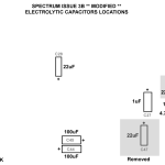
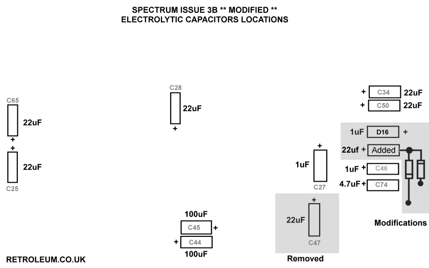
Issue 3B, modified
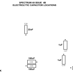
Issue 4B
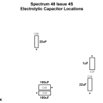
Issue 4S
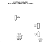
Issue 6A
Special considerations for Spectrum Issue TWO boards:
- As C27 and C47 are located right next to the heatsink on Issue 2 boards, they will be subject to stress from the higher temperature and may have reduced life expectancy. Capacitors rated for 105°C were recommended when servicing but unfortunately these are now extremely rare if not impossible to source new in the axial format. Radial types are therefore pretty much mandatory if you want to add this precaution. Another way around the heat issue is to replace the 7805 Voltage regulator IC with a modern switch mode type – these are available at the store under ‘Spectrum Mods’.
- There is a printing error at C46! The board is marked with +ve on the right – this is incorrect. The 1uf Capacitor should be mounted with its +ve lead on the left.
- A 22uf capacitor is recommended for C65, with its +ve lead to the right (early boards had a ceramic type so the polarity is not marked on the PCB)
- If the DC-DC mod is made on this board, a radial 4.7uf cap will be fitted with its +ve lead connected to the top lead of C34 and negative to the left lead of R58. (The 100 Ohm resistor at R60 will also be replaced with a 270 Ohm)
- More info on the Issue 2 board can be found here
Issue 3B modification:
- The DC-DC converter circuit was often modified for reliability on issue 3B boards. The locations of the caps used in the mod varies but you will find that diode D19 is replaced with a 1μf capacitor (+ve lead to the right), C47 is removed, and a new 22uf cap added with its -ve lead connected to the junction of two BA157 diodes. (See the diagram above).
Misc:
- For information on the composite video mod, go here