-
Spectrum Issue 2 PCB mods
 Sinclair came up with various modifications to their Issue 2 Spectrum PCBs which were often applied if they came in for servicing. You may wish to apply these whilst re-capping / refurbishing if they’re not already present. (Incidentally, the parts required are now included as standard in my Spectrum re-capping kits)
DC-DC converter mod.
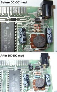
The circuit that generates the voltages for the lower RAM was found not to be very reliable (TR4 blowing). The following fix is often seen on Issue 2 boards.
- The 100 Ohm resistor at R60 is replaced with a 270 Ohm resistor.
- A 4.7uf radial capacitor is added, with its +ve lead soldered to the top lead of C34 (22uf) and its -ve lead to the left lead of R58 (1K Ohm) – Keep its legs short so it fits in the case, away from the edge connector.
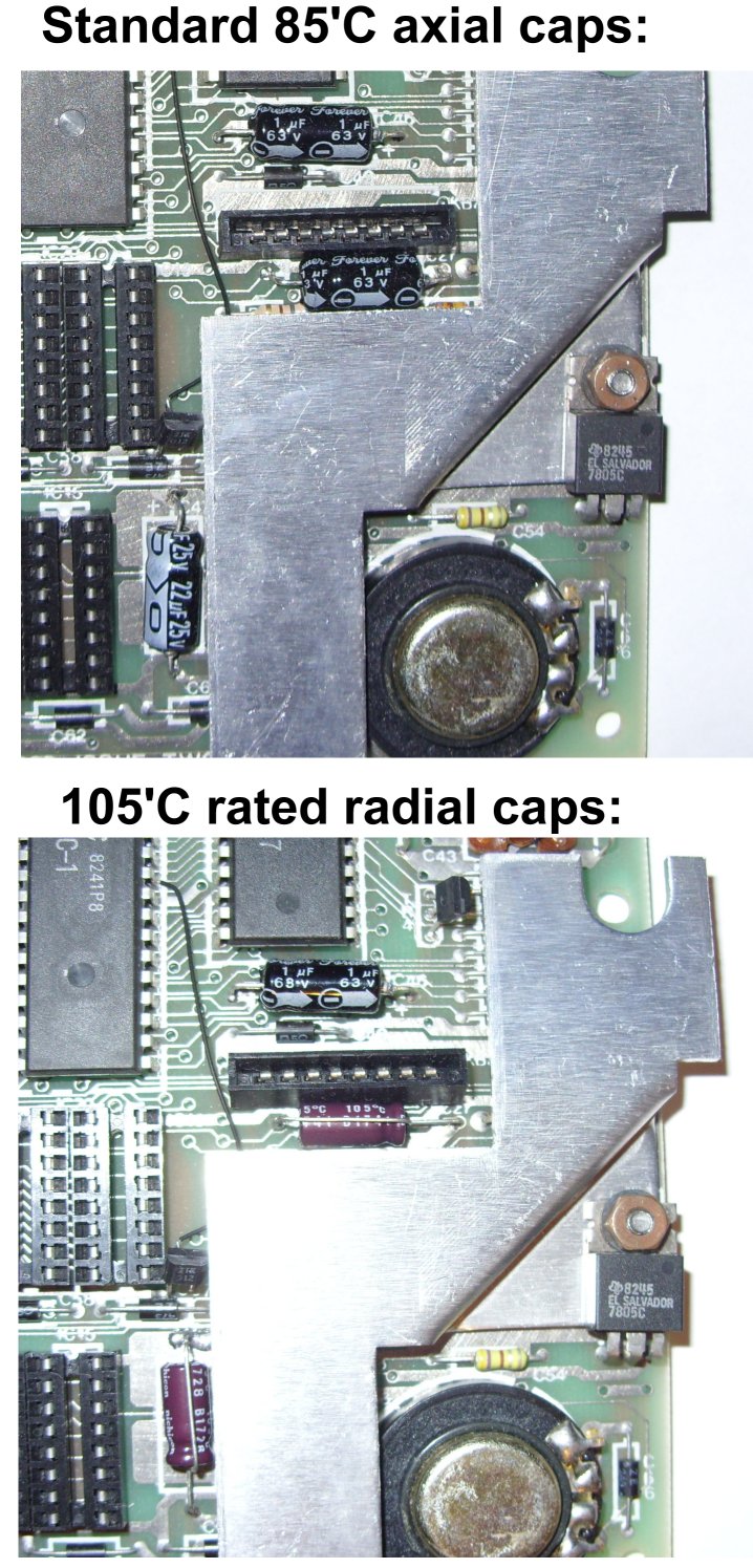
105°C rated capacitors at C27 (1uf) and C47 (22uf)

As these capacitors are located right next to the heatsink on Issue 2 boards, they’re vulnerable to stress by the higher temperature and may have reduced life expectancy. Capacitors rated for 105°C can be used when replacing them but unfortunately axial types are now extremely rare if not impossible to source new, therefore radial types are pretty much mandatory if this mod is done. To mount them, simply bend the longer (+ve) lead over the body of the cap and lay them horizontally with the exposed lead uppermost, observing the correct polarity marked on the PCB.
Another way around the heat issue is to replace the 7805 Voltage regulator IC with a modern switch mode type – these are available at the store under ‘Spectrum Mods’ – the heatsink is not needed afterwards.
Other notes regarding issue 2 boards:
- There is a printing error at C46! The board is marked with +ve on the right – this is incorrect. The 1uf Capacitor should be mounted with its +ve lead on the left.
- A 22uf capacitor is recommended for C65, with its +ve lead on the right (early boards had a ceramic type so the polarity is not marked on the PCB)
- These boards have 200 Ohm Speakers, later issues use 40 Ohm speakers.
- Issue 2 boards have trimmers (TC1, TC2, VR1, VR2) to set the colour balance, whereas later versions have an active system which handles this automatically.
- Issue 2 boards usually require louder input for loading than later versions.
- These boards have a default modification to correctly handle port decoding. This was usually achieved with a ZTX313 transistor mounted across the body of the CPU (known as the “spider mod”) with its collector to 5v, base to CPU A0 and emitter to ULA pin 33. (The transistor can sometimes also be found mounted elsewhere and occasionally an alternative diode and resistor arrangement was used to achieve the same result.) This mod was incorporated onto the PCB on later versions as TR6.
- The CPU clock driver was modified. The original 100 Ohm resistor R24 was replaced with a 1K resistor, and diode D14 replaced with a 100pf capacitor. In addition, a 1K resistor was added from ULA pin 32 to 5v. Again, these mods were incorporated into the standard circuit on later boards.