-
Spectrum Video Mods
It is possible to modify the original ZX Spectrum’s video output to give a composite video signal through its standard phono jack – this gives a much improved picture and is more compatible with modern TVs (which may not have an analogue RF tuner).
There are three main methods of doing this: The simplest way is to just connect the composite video signal from the PCB direct to the phono socket pin with a wire (after desoldering the resistor connected to it). A variation of this uses a capacitor (typically a 100uf 16v type) instead of the wire (which improves compatibility on modern TVs). Alternatively, a transistor can be used (this buffers the Spectrum’s video circuitry and gives a brighter picture by default but may not work on all TVs). If care is taken, all these mods can be easily reversed if necessary.
Naturally, after modding a composite video cable should be used to connect the Spectrum to the TV instead of the RF lead. The components required are available from retroleum.co.uk (and are included as standard in the Spectrum re-capping packs)

The capacitor version is detailed here (obviously just replace the cap with a wire you want the simplest version:)
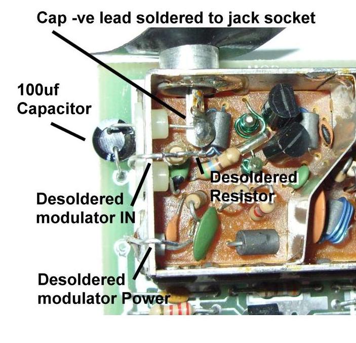
1. Pop the lid off the modulator box and de-solder the top end of the resistor that is connected to the jack socket pin.
2. Desolder the modulator’s input and power leads (on the left of the box). Make sure the topmost PCB pad is clear of solder.
3. Bend the capacitor’s leads so that it can mounted as shown. You can pre-trim the +ve lead (the one without the white stripe on the capacitor’s body) so it is easier to fit.

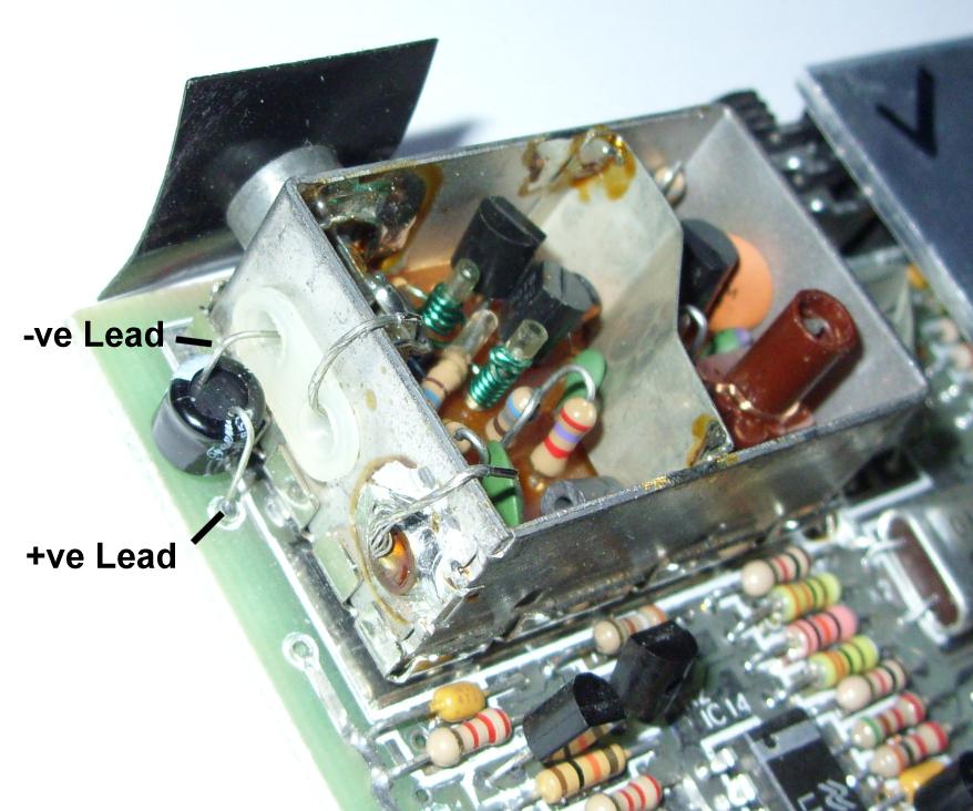
4. Install the capacitor, passing the -ve lead through the topmost grommet in the modulator.
5. Solder the -ve lead to the phono jack pin where the resistor was originally connected and the +ve lead of the capacitor to the video out pad on the Spectrum motherboard .
6. Bend the modulator’s original wires over the side of its case and clip the lid back on the modulator, trapping the wires out of the way.
7. Optional: If you find the brightness is a bit dark, you can boost it by replacing TR1 and TR2 with BC549C transistors, but note: they must be orientated 180º compared to the originals, ie: the shape of the transistors should be opposite to the footprints marked on the PCB (ignore the text on the transistor bodies). Nothing will be damaged if you get it wrong, but the picture will be very dark. Bear in mind this brightness mod should should only be done on composite video modded boards, as it tends to create white flaring in the original RF output.
Transistor Video Mod:
1. Pop the lid off the modulator box and de-solder the top end of the resistor that is connected to the jack socket pin.
2. Desolder the modulator’s input and power leads. Make sure the holes in the PCB pads are clear of solder.
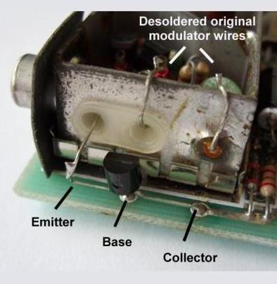
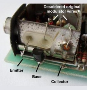
3. Bend the transistor’s leads so it can mounted as shown – The flat side of a BC549C transistor body must face the modulator (the pin layout of other transistor types will vary!)
4. Install the transistor and solder the collector and base leads, trimming off the excess on the underside of the board. Please note: Some Spectrum PCBs have exposed tracks running below where the transistor is mounted – make sure these are not shorted by the transistor’s leads!
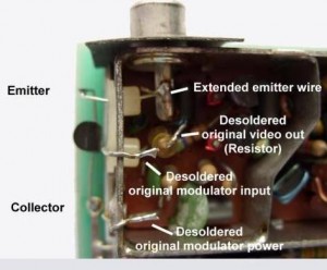
5. The emitter wire will be too short to pass through the grommet in the modulator body so use a small piece of wire to extend it. It may be easiest to pass this through the grommet, soldering one end to the jack socket and the finally soldering the free end to the transistor’s emitter.
6. Bend the modulator’s original wires over the side of the modulator and clip the lid back on the modulator, trapping the wires.