-
PAL TV timing and voltages
Note: No guarantees as to the accuarcy of any of this info – its just what I have gleaned from around the web / datasheets etc (but it worked for me:). Also, there’s no info here on using colour-burst encoding for a composite-mode colour signal (see links below for that), its much easier to use the RGB mode – so that’s what I did.
Timing:
There are 625 horizontal lines in a normal (ie: non-high definition) PAL TV “frame” (though not all of them are actually visible as some are used for vertical sync, teletext data etc). The TV updates the display 50 times per second, however only half of the vertical resolution is available per update – so the TV alternates between two “fields” – the first field writes only the even lines to the screen and the second field writes the odd lines. The second field is said to be “interlaced” between the first field’s scan lines; basically the raster beam is offset half the thickness of a scanline every other field. This process creates flicker because half the total image detail is actually missing each update. Persistance of human vision helps to disguise the effect and it isn’t noticeable so much on “real” video but can be a nuisance if you want a non-interlaced display as used on 80’s home computers, games consoles etc. Apparently there is no official PAL standard for this but its easy to implement – more later.
As mentioned, some lines are actually outside the visible screen. On my TV, the first line visible right at the top of the screen is roughly 28 scan lines* down from the vertical sync, and the window lasts 266 lines, leaving 10 lines outside the CRT at the bottom. The figures vary slightly on each TV – to be sure of a completely full vertical display on all TVs, some extra lines should be used at the top and bottom. A window of 288 lines – which is a common video capture resolution setting – should guarantee a full vertical display. *Note the the figures given here refer to the scan line count of a single field (which have 312 or 313 lines total including the sync).
 Each scanline lasts 64 microseconds (so the horizontal sync frequency is 15625 Hz), of this 64 microsecond period, only the latter 52 microseconds contains picture data (and some of that is not visible). The first 4 microseconds of a scan line are taken up by the horizontal sync signal (a low pulse) and following on are 8 microseconds of what is known as the “back porch” (this holds colour burst data for composite signals and is not used in RGB mode – the 8us delay still needs to be there though). As mentioned not all of the line is visible, the first and last few microseconds of each available line are normally outside the edges of the visible screen but can be used to ensure a full horizontal display on all TVs. On my TV, the first visible pixels appear at around 1.25 microseconds after the backporch period and the visible line lasts about 48.5 microseconds. Note that the horizontal pixel resolution is not fixed, so within reason you can use whatever speed pixel clock you want. Of course, you normally want your pixels to be as square as possible and a common pixel rate used in DVD players etc is 14.75MHz (so 7.375MHz for non-interlaced pixels). I used an 8MHz clock throughout my Z80 project – this made the time divisions for the sync periods etc simple integers – and the pixels were not noticably rectangular.
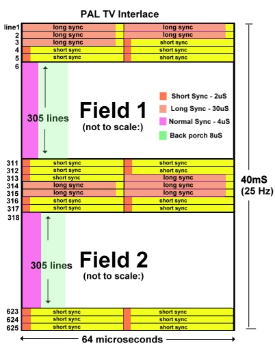
Vertical sync is obtained from the last few and first lines of each field. These lines contain a series of special sync pulses which differ on alternate fields: –
The format for field 1 (starting at line 623.. ends at line 5 inclusive):
- 6 Pre-equalizing pulses.. 5 long sync pulses… 5 Post-equalizing pulses.
The format for field 2 (starting at line 311.. ends at line 317 inclusive):
- 5 Pre-equalizing pulses.. 5 long sync pulses… 4 Post-equalizing pulses.
The pre- and post- equalizing pulses are “short syncs” (active low as usual) of 2 microseconds followed by a delay of 30 microseconds – therefore they last half a scanline each. The “long syncs” are 30 microsecond low pulses with a 2 microsecond delay after them, they last half a line each too. The different vertical sync pulse trains of each field is the means by which the raster beam is offset half a scan line for the interlacing.

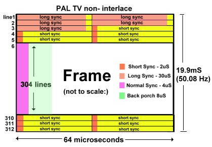
You can stop the display being interlaced if you want – the solution appears to be to just use the same sync pulse train each field, ie: the 6-5-5 one from ‘field one’ (which lasts 8 whole lines). I’ve seen it done like this in chip data sheets and tested it with my Z80 project (also confirmed with a oscilloscope connected to a Playstation2 running a non-interlaced game). The only ‘problem’ is that you’re now dealing with 2 fields of 312 lines instead of 312.5 – which means you get a frame rate of 50.0801Hz instead of 50Hz – but TVs don’t seem to have a problem with it. Presumably its possible to alternate between two different sized frames (312 and 313 lines) to maintain the 50Hz average but I’ve not tried it.SCART Pins and Voltage specs:
Sync / Composite Video In (Scart Pin 20): The sync pulses are active low signals on the composite video line: 1.0 volts = White. 0.3 volts = Black, 0 volts = Sync (“blacker than black”) So in RGB mode the line is normally 0.3v, pulsed to 0v for the sync periods.
Red (Scart Pin 15), Green (Scart Pin 11), Blue (Scart Pin 7) Inputs: 0.7 volts = peak intensity of colour, 0 volts = lowest intensity of colour. Note: I’ve found that my TV does weird things if there any voltages above zero present on the RGB lines during the sync / back porch periods (stuff like switching out of RGB scart mode, treating the colour present during sync as a black reference) so it seems its necessary to inhibit your RGB outputs during those times.
RGB mode select (“Blanking” Scart Pin 16): Some TV’s let you toggle RGB mode via the remote but to force it, put 1 to 3 volts on this pin. (5 volts via a 100 Ohm resistor will set it at 2.1v due to the 75 Ohm load in the TV)
Note: All video (and control) signal lines see a 75 Ohm impedance at the TV end.
Video Ground: Scart pin 17.
Audio in (if required). Scart Pin 2 – left channel (or mono), Scart Pin 6 – right channel: 1 Volt peak-peak signals (about 20K Ohms impedance)
Audio Ground: Scart pin 4.
Further Reading:
- The 625/50 PAL Video Signal and TV Compatible Graphics Modes
- Analogue Video
- Rickards Pic Page
- Doom9 Analogue Video
- SCART pin-outs

