-
EZ80P
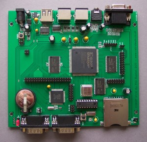
The EZ80P is an original open source 8-bit hobby computer I designed based on the Zilog EZ80L92 CPU and a Spartan 3 XC3S200 FPGA.
It’s not really a successor to the V6Z80P– it’s just different.. For example, the board is expandable, having several pin headers dotted about and is better equipped for VGA resolution output. At 50MHz, the eZ80 CPU is a lot faster than the original Z80 and it has a 24-bit address bus so can access 16MB of address space without paging thanks to an enhanced Z80 instruction set. On the other hand, the EZ80P is not suited to emulating classic 8-bit systems since the CPU (actually it is more of an MPU) is not 100% compatible with the Z80 (its peripherals are hardwired to certain ports, there’s different interrupt handling etc). It does run standard Z80 code however, in 64KB pages.
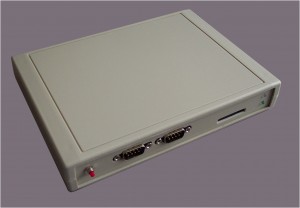
The EZ80 chip has lots of general purpose port pins – I’ve routed 12 of these to the DSUB-9 connectors at the front for use as joystick inputs, but they can be reconfigured as general purpose IOs for general hobbyist tinkerings via software (there is a pin header for the other unused eZ80 IO pins).
For on-board memory there are three 512KB (4Mbit) 10ns SRAMs, one is connected to the eZ80 bus (and FPGA) and the other two are completely separate, connected directly to FPGA pins. (The third SRAM’s pins are also connected to pin headers, meaning the relevant FPGA pins could be used for general purpose I/O if desired).
For PC communications I’ve used an FT232RL USB-to-Serial chip and a standard USB socket. The Ez80P is treated as a virtual com port by a host PC (there are drivers for Windows, Linux & Mac).
Like the V6Z80P, I’ve made my own default FPGA config (cheekily called AMEOBA – “Another of My Eight Bit Architectures”) and Command Line Operating system. AMOEBA only supports VGA output and as I dont have a decent camcorder demonstration videos are not easy to make. So for the time being here’s run down of the project’s features.. Full documentation, source code etc is in the project archive. Applications can be developed using Zilog’s free ZDS II software (which includes support for C programming)
EZ80P Features:
Spartan3 XC3S200 FPGA
50MHz EZ80L92 CPU (clock supplied by FPGA)
25MHz system clock (can be doubled by FPGA for CPU)
512KB CPU bus SRAM #1, 10ns
512KB SRAM #2, 10ns (independent bus 1, direct connection to FPGA)
512KB SRAM #3, 10ns (independent bus 2, direct connection to FPGA and header pins)
4MB EEPROM (holds up to 32 FPGA configs or other data)Connectors:
15 pin Standard VGA connector (12bit RGB colour)
Stereo 3.5mm audio socket
SD Card connector with access LED
PS/2 Mouse Connector
PS/2 Keyboard Connector
USB Connector (FT232RL Virtual Com Port: RX,TX,CTS,RTS implemented)
2 x DSUB-9 Joystick connectors / General purpose eZ80 IO ports (each: 6 pins IO, 5V/3.3V and GND)
2032 lithium battery holder for RTC backupDefault Operating System PROSE – “Phil’s Rudimentary Operating System Experiment”
A simple command line / debug / freezer-cartridge-like OS.. thing (based on the V6Z80P’s FLOS)
Supports Z80/ADL code (Z80 code: 64KB pages)Default Architecture: AMOEBA – “Another (of) My Original Eight Bit Architectures”
Bitmap chunky mode: 640×480, 320×480, 640×240, 320×240 in 16 or 256 colours
Tile map mode : 640×480, 320×480, 640×240, 320×240 in 256 colours
Text mode: Resolutions as above, 16 colour character+attribute mapping.
Sprites : 256 colours, 16 pixels wide/ any height, 128 sprite registers, 40 per scan line
Video Output: VGA 60HzAudio: 8 sound channels (4 to left side, 4 to right side) plays 8-bit signed samples (individual frequency,volume, start, length registers)
Pin Headers:
40 pin : Main bus / memory expansion (MREQ, IOREQ, RD, WR, a control line from FPGA,A0-A23,D0-D7 plus 3.3v & GND)
14 pin : EZ80 unused port pins (PB1-PB7,SDA,SCK,PHI, plus 3.3v + GND)
16 pin : 14 FPGA IO pins (also used for SRAM3) plus 3.3v & GND
20 pin : 16 FPGA IO pins (also used for SRAM3) plus 3.3v & GND * 2
2 pin : Spare FPGA IO pin 1 plus GND
2 pin : Spare FPGA IO pin 2 plus GND
6 pin : External Reset/Status LEDs
2 pin : External Soft power button.
2 pin : SD card access external LED
6 pin : Standard JTAG connector (TMS,TDI,TDO,TCK,GND,3.3v)
3 pin : Joystick / IO pin voltage/pull-up select: 3.3v or 5vMisc:
CPU clock, NMI, WAIT, BUSREQ controlled direct from FPGA pins.
Maskable interrupt line connected from FPGA to eZ80P PB0.—
The Ez80P is no longer in production – with boards like the Raspberry Pi now available (incredibly cheaply), the EZ80P has lost much of its raison d’etre.


