-
How To Replace The ROM Of A ZX Spectrum With An EPROM

PCB mod summary
Replacing the ZX Spectrum’s ROM with a standard 28 pin DIL EPROM (such as the 16KB 27C128 or 32KB 27C256) is fairly straightforward, but it does require a few physical modifications to the PCB:
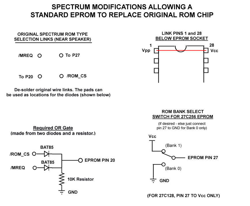
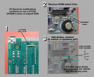
1. With the original Spectrum ROM, pin 1 is not used but on an EPROM it is the Programming High Voltage pin: For normal READ-only operations this needs to be pulled up to Vcc. You can simply solder a wire link from pin 1 to pin 28 on the back on the Spectrum PCB.
2. The arrangement of /ROM_CS and /MREQ is different for EPROMs and it even varies across the original ROMs Sinclair used, hence there are selection links on the Spectrum PCB with 4 connection points. These are convenient as it means no tracks need to be cut once the links are de-soldered – all the signals required for the next part of the modification are available as solder points.
Essentially, you need to make an OR gate, its inputs being /ROM_CS and /MREQ and the output going to EPROM pin 20. The OR gate can be a simple diode and resistor affair, Schottky diodes are recommended (EG: BAT85) as they have a lower voltage drop than plain silicon diodes but the ubiquitous 1N4148s have been known to work. A value of 10K for the resistor should be fine. (Note: I have seen Spectrum motherboards where the ROM has been replaced with an EPROM sometime in the past, but pin 20 has simply been connected to /ROM_CS without forming an OR gate with /MREQ – This is bad: The Spectrum appears to work normally but there will be a keyboard issue if a program reads from port $00fe (EG: to detect any key press in one operation) – ROM data will be put on the databus during the read, overruling that supplied by the ULA from the keyboard. One such program where this problem manifests itself is Zynaps – the game starts itself after a few notes on the title tune without user input.)
Spectrum EPROM ROM Replacement – Photo guide
3. Finally, EPROM pin 27 needs to be connected. In the case of the 27C128 chip it should be connected to Vcc. For the 27C256 chip it can be used as a “ROM bank select” since the chip is 32KB in size and pin 27 is used as Address Line A14. When connected to GND, Bank 0 ($0000-3fff of EPROM) is selected and when connected to Vcc Bank 1 ($4000-7fff of EPROM) is selected – a SPDT switch can be fitted to provide a simple selection method if desired.
PS: I made a diagnostic ROM image which you can read about / download here.