

-
Getting Reacquainted With The Commodore 64
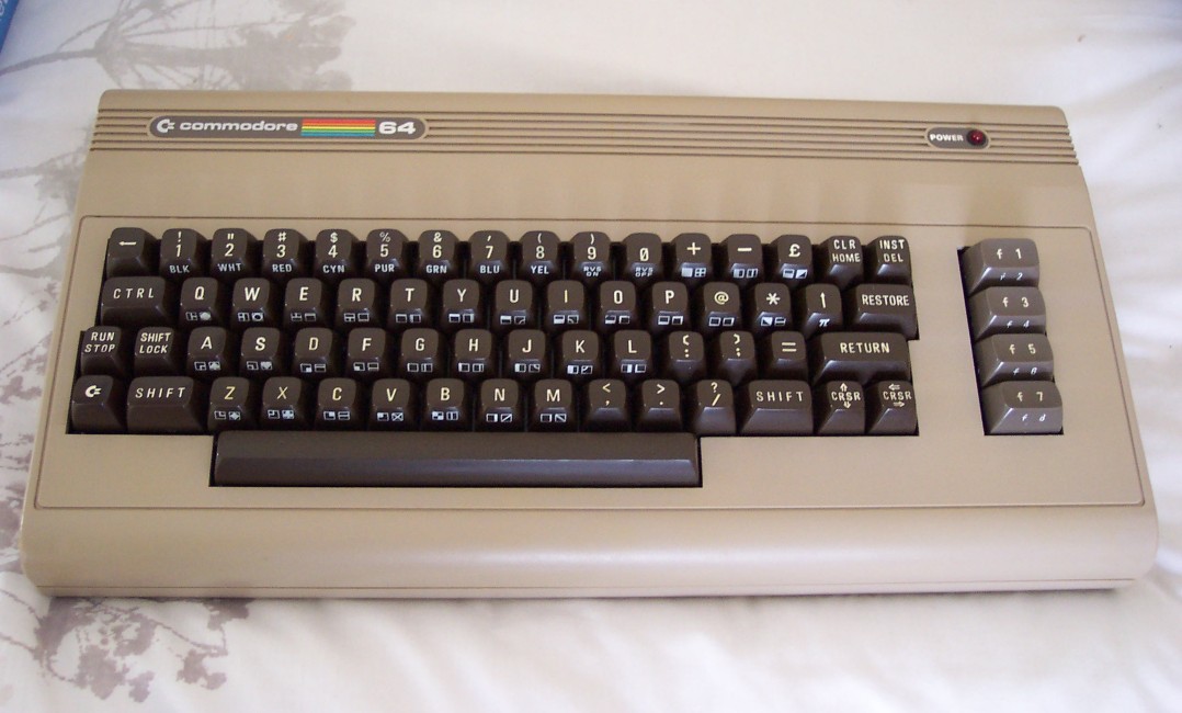
C64 – Scrubbed up quite nicely!
I’d been meaning to get myself a Commodore 64 again for some time.
I sold my original set-up twenty-odd years ago and of course regret it as it’s so much better to keep your own gear. Anyway, a friend’s fledgling retro computer collection nudged me toward ebay and a C64 with various bit and bobs was duly acquired.
On arrival, the C2N tape deck appeared to be dead, but this turned out to be caused simply by gunk on the connector. I think it’s pretty mandatory that the first thing to do on acquiring a C64 is to open it up, lightly vacuum away any loose dust (bits of wire, food, fossilized spiders..) and clean the gold fingers of the expansion ports. For this I used the “pen” end of a pencil eraser (where the dirt was stubborn) and then cleaned up with isopropanol on cotton buds.
Cosmetically, the machine was in good condition – the case hadn’t yellowed much so I was spared any adventures with Retr0bright :) The customary surface grime was removed (after completely dismantling the case) with warm soapy water and the keyboard was cleaned with some compressed air and cotton buds between the keys.
White flare / Colour bleed in RF output
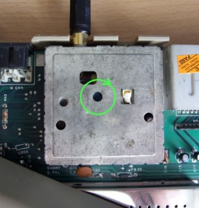
The only other hardware issue was a bit of white flare in the RF-output. I’d seen this on a C64 I’d had back in the day and remember solving it with a tweak of one of the TV modulator’s trimmers. Sure enough, it was soon cured (centre pot, very slightly turned to the right).
I’d always used RF for the video output originally so I was curious to see how the Composite and S-video signal would look. SCART cables for the C64 are widely available on ebay etc, but it didn’t look like they offered the S-video switch so I made my own following the diagrams here.
The results were.. mixed. S-video was a disappointment with barely any colour content to the video until I removed the optional 330 Ohm resistor from the chrominance line (this was tested on two separate CRT TVs). Afterwards, things improved a little but it was still pale and not particularly crisp. The Composite output looked very much like RF, just a little sharper. To be fair, the analogue tuner in my TV is excellent so I guess there was little scope for improvement there.
Turn to fix the RF white flare
Neither of the SCART outputs really improved what seems to be a internal design issue with the VIC-II chip: Some colours always look bad when placed next to each other, and there’s still vertical banding and chroma confusion with finely detailed graphics (a pixel-checkerboard pattern shows this quite badly). I’m not certain if these things were ever improved much in the later versions of the 64 – the VIC chip certainly has its quirks.
There was a surprising difference in the sound output. Having been used to the C64 sound via the RF signal, I was surprised how crisp SID sounded via the A/V port. I’m not sure I like it – the sound is noticeably low-pass filtered via RF (“bassy” or “muffled” depending on your taste) and to me, at least, this gives it a warmer, richer feel (don’t worry, that’s as close to audiophile terminology as I go!)
So yeah, a SCART cable is a nice extra to have around but honestly if your TV’s analogue tuner is half decent and the C64’s RF modulator works OK (they do degrade) – you’ll be fine with that.
Disk Dilemma:
The next step was to decide what to do for loading. (After testing some tape games to put on ebay, the C2N was soon packed back in its box :) The solutions appeared to be..
1. An actual Commodore 1541 disk drive (about £35 on ebay)
Advantages : Total compatibility.
Disadvantages: It’s a 1541 so constant disk-alignment issues. Faffing about with physical 5 1/4″ floppy disks.2. An SD-card based emulator (such as the SD2IEC – about £45 )
Advantages : Can plonk tons of disk images on one card.
Disadvantages : Not a cycle-perfect emulator, so custom loaders will mostly fail. Same speed as a 1541, unless you have a turbo-load cartridge installed or use a software bootloader that is compatible with the SD2IEC.3. A “1541 Ultimate” cartridge (about £100)
Advantages : Perfect 1541 emulation. Freezer cart emulation etc. So many features – this thing is awesome!
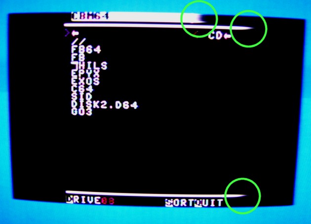
Disadvantages : Price, not readily available.I went for an SD2IEC as I wanted something soon and didn’t really want the hassles of a physical 1541. The SD2IEC is a neat little unit boxed to look like a miniature 1541 drive, it has two connectors, one for the serial port and one for the cassette port for power (you can also get a version that takes power from the user port if preferred). Upon power up you can access it pretty much like a normal 1541, so for example LOAD “$”,8:LIST will show the root of the SD card.
As mentioned, the device only approximates a 1541 so disk images of original games with custom loaders will probably not work. Fortunately the SD2IEC website offers a handy file archive containing working versions of almost everything! Also as mentioned, by default the speed is the same as a real 1541 (IE: terrible!) but you can use turbo load via a cartridge like the Epyx Fastload or Final Cartridge 3, a kernal replacement (JiffyDOS) or a software DOS patch. I found that EPYX and EXOS work fine as software options but unlike a hardware solution you have to keep loading them each boot. This is a little bit of a pain, since you need to..
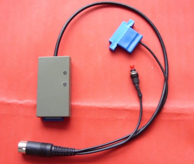
SD2IEC – Modified with C64 reset button
LOAD “EXOS”,8
RUN
LOAD “FB”,8
RUN..and then browse to the file you want to load, but it’s better than waiting a couple of minutes for something to load with the standard Commodore loader!
The one additional thing that the SD2IEC could do with is a button to reset the C64 (its buttons are used to swap virtual disks and reset the drive only). As my C64 is an early model I knew it would reset via the serial port so I modified the SD2IEC’s serial connector with a push button across pins 2 & 6. (Later C64s did not allow a system reset this way, you needed a User Port or Cartridge Port based reset button).
Ruggedizing!
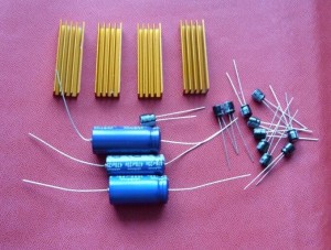
C64 replacement capacitors. Plus heatsinks.
The C64 was a pretty well-built machine but with the best will in the world some components wont be in great shape after 30+ years. The C64 has a fair few electrolytic capacitors inside and they’re known for drying out and degrading over time. Therefore my next job involved removing all the caps and replacing them with brand new ones (as I also did with a ZX Spectrum I acquired recently). For my early model C64, I needed:
1 x 2200uf 16v axial
1 x 1000uf 25v axial
1 x 470uf 25v axial
1 x 100uf 16v radial
12 x 10uf 25v radial(There were many C64 board revisions – I now sell capacitor sets for most of them at my store)
It’s pretty a straightforward job to de-soldering old large components like these, the key is to have the right tools:
1. A soldering iron of sufficient wattage to re-flow the solder on pads that are connected to thick ground traces (Something about 30 watts should be OK).
2. A de-solder tool / pump.
3. Optional: Some de-soldering braid and flux to clean up pads before re-soldering.
The only other thing to watch for is the polarity of the capacitors, they must be fitted the right way around. The board is well marked with + and – and capacitor bodies are always marked with a stripe with arrows pointing to the – end (and in the case of axial types, the ‘indented ring’ is at the + end.)
Whilst I had the PCB out, I wanted to add heat sinks to the two chips that run hot and fail the most on C64s, namely the SID 6581 and PLA 906114-01 – this wasn’t essential, but I wanted to give them the best chance of a long life. (The VIC-II chip (6569 in the UK, 6567 in the US) also runs hot but this normally has some form of heatsinking already. It’s usually hidden from view in a shielded cage – the top of which has a copper tab that touches the top of the chip via some thermal paste. If there’s no reason to believe this has been disturbed, it should be OK to leave it alone. Note: I have read of a C64 board revision that provided no heatsinking for the VIC-II chip!)
You can get heatsinks suitable for DIL chips like the SID and the PLA (also available at the store :) but I had some old chipset coolers from PC motherboards which I cut down to size and dressed up a bit. As there are no clips and you want the heatinks to stay in place (and not, say, fall off and short out everything in range:) you need some method of ‘permanently’ attaching the heatsinks to the chips. Some options:
1. Thermal adhesive tape / pads.
2. Thermal glue – the most permanent solution.
3. Standard heatsink compound and epoxy resin (Araldite) – a bit ghetto.The thermal adhesive pads are probably the least hassle. I could’ve just used a smear of standard heatsink compound (or Arctic Silver) in the centre of the chips and a dab of epoxy resin top and bottom but I wanted to make a permanent job of it so I bought some Arctic Alumina thermal glue. Application was simple: I first cleaned the top surface of the two chips with isopropanol on a cottom bud, mixed up the two-part adhesive, spread a thin layer on the chips and placed the heatsink on top, squishing it around a bit with a slight circular motion. A put a little weight on the top for an hour whilst it dried.
Power Supplies:
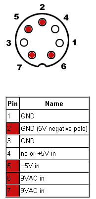
The final issue for modern day C64 users is the threat of the PSU suddenly dying and taking out the computer. This seems to be a controversial area of discussion with some people swearing by the original ‘door wedge’ linear Commodore PSU and others suggesting it’s a time bomb. My own feeling is that after 30+ years the status of its components have got to be dubious, especially with the heat it famously chucks out. However, if you check the voltages occasionally (before and after use) with a multimeter, they’re in spec and there’s no operational weirdness afoot you can probably relax a bit. The 5V DC line is the critical one, it should be around 5.2 v DC off load, certainly no higher than 5.4 V DC. It’s worth bearing in mind that Commodore modified the PSU’s internal 7805 regulator circuit to supply around 5.2v – this was to overcome voltage drops in the cable, power connector and switch. If you test the 5v power pins inside the actual C64 when powered up you should find it nearer 5v. (Third party PSUs often had the standard, unmodified 7805 5.0V output but used shorter power leads to avoid too much voltage drop.)
PSU Repair.. CAUTION! Should only attempted by those comfortable with working on devices that are mains powered. With care, some original C64 PSUs can be refurbished. The later cuboid “finned bricks” are totally filled with resin so are pretty much fit for the bin when out of spec, but the wedge-like types are only partially resin-potted. The lower part of the case can usually be removed by cracking along the seam (starting at the front) and if necessary breaking some support pillars. Access to the diodes, capacitor and voltage adjustment resistors (but not the 7805 regulator itself) is then possible. (A low-heat switch-mode regulator can be used to replace the 7805 circuit if desired – EG: A UBEC 3Amp DC-DC converter module or OKI Murata 1.5 Amp type though I’ve not tried this myself and I’d be cautious of recreating the under-voltage problem cus AFAIK it’s not possible to tweak the output of such modules.)
As far as new Commodore 64 PSUs go, with the notable exception of those Ray Carlsen the market is pretty much non-existent. Main powered devices are mired in safety regulations etc but there’s nothing to stop you making your own.. You’d need a 5V DC PSU board with over-current and over-voltage protection capable of outputting 1.5 Amps, together with a transformer that will supply 9V AC at 1 AMP. An alternative is to use an original PSU and obtain or construct a “Computer Saver” which cuts the power if the voltage rises above a pre-set level, an example of such a circuit can be found here.
Coding Capers:
I hadn’t done any C64 coding for a couple of decades, so I was quite eager to reacquaint myself with the foibles of the 64 (especially as one of my 64s came with the Programmer’s Reference Manual). Back in the ’80s I did all my 6502 coding using only an Expert Cartridge, entering code entirely in hex (it wasn’t very hard to memorize the entire set of 6502 opcodes). These days I draw the line at THAT much of a retro experience and use cross-assemblers on the PC. I imagine I’ll probably mostly use an emulator like VICE for testing and check things occasionally on the real C64.
For my Z80 coding I use a Windows-based text editor called Programmer’s Notepad (mainly because I found a syntax highlighting scheme for that CPU). I had no such luck finding one for the 6502 instruction set and I wasn’t having any joy creating my own. Eventually I settled on another freeware editor called ConTEXT – this ticks all the boxes: 6502 highlighting built in, external program launcher for assembling, output capture console etc. (The tab handling is a bit bizarre by default, but is easily remedied in the options).
That just left the actual 6502 assembler which I’d be calling from the editor – there’s quite a few out there so I was able to pick one that matches my particular coding style (must have an “include binary” directive, non-picky label naming conventions etc) For this, ‘DreamAss‘ fitted the bill.
So.. That’s it.. better do a bit of coding I guess! :)
As mentioned, I now have a little spares shop should you require replacement components for the Commodore 64.
C64 resources:
- Codebase64.org – Coding info, tools, books etc
- Lemon64.com – Game info, discussion forums etc
- CSDb – The Commodore 64 Scene Database

