-
PSone LCD info
The Sony PSone LCD screen is popular among PC case modders and console hackers as it accepts standard RGB and composite TV signals. Its also cheap (I got mine for £35 off ebay) and easy to take apart if necessary (the cold cathode back light can be replaced with white LEDs if need be). The screen comes with a 7.5 volt 3 Amp A/C adapter (a beefier unit than that originally supplied with the PSone) and is designed to physically dock at the back of the PSone (it has video and power pass through connectors as can be seen in the following pics..)
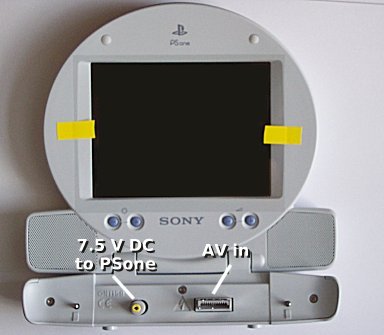
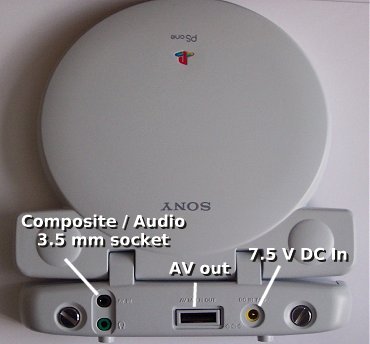
There are many sites on the net which describe removing the case and soldering to the PCB – this isn’t absolutely necessary though especially if you want to preserve your warranty whilst testing. Here’s three ways to connect up the screen to your project without opening the case:
1. Chop up a Playstation multi-AV lead and use the female end to connect to the front of the PSone screen.
2. Get an old (bust?) Playstation and desolder its AVconnector from the PCB, use that in the same way as above.
3. If you can make do with (or only want to use) a composite signal (say from a PC’s TV-out port) – you can get a 4 pole 3.5mm jack plug, wire it up and connect that to the rear of the PSone screen. (Here’s a guide for that.)
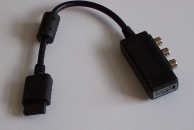
I needed an RGB connection so it was option 1 or 2 for me. I have got a bust Playstation kicking around but I also discovered a Playstation video splitter / pass-through cable in my junk box. Like this:
After cutting the cable in half, discarding the male end and stripping the wires, it was a just case of finding the pin-outs for the screen and seeing which colour wires were required. Naturally the pin-outs are the same as a Playstation and according to this site, they are:
1 – Ground
2 – Audio right
3 – Ground
4 – Audio Left
5 – S Video Y (IMHO: “PAL SYNC” – SEE IMPORTANT NOTE)
6 – NTSC video / Composite Sync (IMHO:”N/C” – SEE IMPORTANT NOTE)
7 – S-video C
8 – Video Ground
9 – Blue
10 – 5 volts (PSone LCD screen sense line, screen powers up when 5V)
11 – Red
12 – Green
* IMPORTANT! Connecting the composite sync to pin 6 does not work in my experience, it should be connected to pin 5. Not sure why most sites say pin 6 is composite sync (perhaps the key means pin 6 is for NTSC period…?)
View of female AV connector at back of Playstation:

         --------------------------
        !                          !
        !  =-=-=-=-=-=-=-=-=-=-=   !
         --------------------------
        Pin 1 ................ Pin 12

View of male AV connector on front of PSone screen:

         --------------------------
        !  =-=-=-=-=-=-=-=-=-=-=   !
        !                          !
         --------------------------
       Pin 12 ................. Pin 1
Whilst testing I wasnt bothered with sound, so I only needed connections to “Video Ground”, “Composite Sync”, “5 volt sense”, “Red”, “Green” and “Blue” – 6 wires in all. I used a multimeter on continuity test to find what colour wire went to which pin (the colours themselves weren’t much of a clue, only red/white for audio and black for ground made sense) and connected them accordingly to my Z80 project’s video out port.
The PSone screen appears to act just like the SCART input of a TV in presenting 75 Ohm loads to the video signals so no interface was required. I connected the PSone pin10 (“power up screen”) to 5 volts via a 100 ohm resistor, this was convenient as I already had this output going to the normal TV connection for SCART pin 16 (“Select RGB mode”).
With my custom cable connected, I plugged the mains adapter into the back of the PSone screen and powered up the Z80 project – the screen’s backlight came on but no picture appeared. I had noticed some ambiguity in the labelling of
Pins 5 and 6 on the internet guides so immediately suspected that was the problem. Sure enough when I connected my sync line to pin 5 instead of pin 6 and powered back up I got a picture :)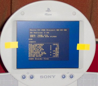
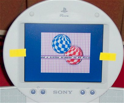
My V3 Z80 Project’s display window is fixed at 256 by 200 pixels hence the large borders. There’s also a tiny bit of sub-pixel jitter (presumably caused by the pixel clock being 8Mhz instead of whatever the PSone puts out). Of course on a cheap screen like this the response time isn’t awesome so there’s a little blur and whatnot in animation but all in all its quite acceptible.
Some more pics showing the internal connections:
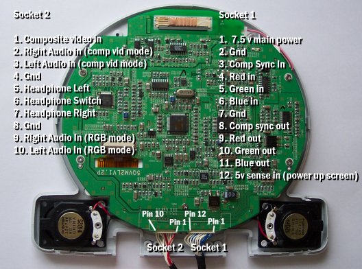
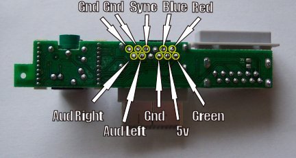
Note: The Headphone Switch line has to be pulled to Ground for the internal speakers to work.
Further reading:

