-
The V4Z80P – A Z80 Based Laptop
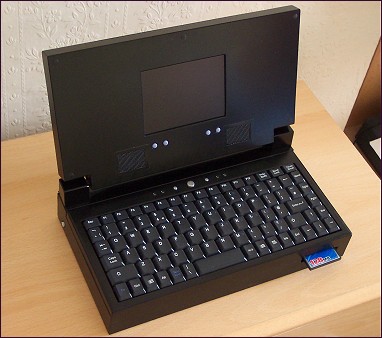
[Please bear in mind this laptop was made as a bit of hobbyist fun around 2006-2007 from odds and ends I had lying around at the time. Sadly, it isn’t something I could repeat let alone mass produce. The PCBs inside evolved into the V6Z80P.]
A Z80 laptop? Why not :) I had reduced the size of my ongoing Z80 project down to something more wieldy by using CPLD chips, but it was still a bit too bulky to fit into an acceptably sized case. The next step was to look into FPGAs and see where they could take it. One thing led to another and I ended up building a self contained post modern home computer laptop.. thing.
Behold the specifications!
- 8MHz Zilog Z80 CPU
- 128KB System RAM
- 128KB Video RAM
- 128KB Audio RAM
- 128KB Sprite RAM
- 2.5″ IDE HDD
- Compact Flash Card Slot
- 5″ LCD display.
- 4 Channel Stereo Sound
- External A/V ports.
- Home-brew architecture, OS and file system..
- 256 Colours on screen from palette of 4096
Main Digital Components:
- 1 x Z80 10MHz Microprocessor (44pin PLCC package)
- 2 x XC2S30 Xilinx Spartan II FGPA (144 pin TQFP package)
- 2 x K6R1008C1D 128KB 10ns 5volt async SRAM (32pin TSOPII package)
- 2 x M5M51008DFP 128KB 70ns 5volt async SRAM (32pin SOP package)
- 3 x 74HC574 SMT 8bit latch
- 1 x 74HCT08 SMT Quad AND gate
- 2 x 24C512 serial EEPROM 8 Pin DIL
- 2 x 29F629 PIC 8 pin DIL PIC
- 1 x ST232 RS232 Voltage <-> TTL Level Converter (SMT “micro” package)
(Parts were obtained from Digikey in the US and Rapid Electronics in the UK.)
Free (Windows) software used:
- Xilinx ISE Webpack 7.12 – To design/compile the architecture for the FPGAs
- Microchip MPLAB 7.31 – To compile the code for the configuration PIC
- IC-prog – To burn the code to the configurator PIC and config file to the serial EEPROM
- FreePCB – To design the circuits
- Viewmate – To produce a track mask image from FreePCB’s Gerber files
- MSpaint* – To edit / print out the PCB masks
- Pasmo Z80 Assembler – To assemble Z80 code on the PC
- Purebasic evaluation – To create simple PC utils (serial download, file converters etc)
- HHD Free Hex editor 3.1 – To edit files in hex byte format.
- I also used Paintshop Pro 5, which was given away free on a cover disk at one point.
Mainboard
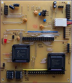 The mainboard has a Z80 CPU running at 8MHz and now uses a small FPGA to handle the system logic. I chose the Xilinx XC2S30 Spartan II for the job as it has 5volt tolerant inputs, useful dual port blockram and was reasonably priced. (A larger FPGA would’ve held a virtual Z80 core of course but I dont have an actual development board with such a chip and I wanted to keep things as familiar as possible).
Whereas the V3 project used microcontrollers for the keyboard interface, serial port and sound system, these features are now done in pure logic in the FPGA. The sound system has been totally revamped and now offers 4 channels of 8-bit sampled sound from a dedicated 128MB sample RAM (it can now play native Amiga protracker modules:)
One area where things went slightly awry was with the IDE interface. I didnt have enough FPGA pins to connect it directly so I used a CPLD to provide the 8<->16 bit interface (and Compact flash friendly) voltage shifting. Unfortunately I was getting uncurable ground bounce which was pretty weird, as it never happened in the previous version of the project. In the end I had to remove the CPLD from the board, desolder its PLCC socket, cut all the tracks relating to the IDE system and patch on a small PCB with an IDE interface made from discrete logic. Kind of annoying, and it bulked things up a bit too.
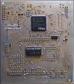
A 8-pin 12F629 PIC and 24C512 64KB serial EEPROM upload the configuration data to the FPGA on boot – not the fastest solution, but cheap and both parts are programmable with the popular ICprog util which I use a lot. The config data also contains the Z80 boot ROM code (it occupies 3 of the FPGA’s block RAMs and is mapped into the beginning of the Z80 address space). The Z80’s reset line is held active until both the mainboard and graphics system have been configured.
I decided to keep the graphics system and mainboard on seperate PCBs early on – it made construction and testing a lot easier. The PCBs (you’ll notice:) are still home-etched, single sided affairs. With the wire links etc, they aren’t the neatest things ever but hey, if you’re going to make a laptop from scratch you cant offload things like that. Also, it works!
GFX board
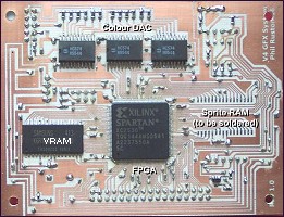 The V4 graphics engine is, like the mainboard, based on a small FPGA (another Xilinx XC2S30 Spartan 2). This has allowed quite a step up in power from the V3 graphics system and also removed the need for the microcontrollers which were originally handling the sprites and timing elements. Briefly, here’s what’s new since the V3z80P..
- Palette increased to 12bit (4096 colours)
- 256 colours on screen at once – 8 bitplanes.
- 16×16 pixel tile map mode with dual playfield
- Number of sprites per line increased to 56
- Simple blitter – much faster moving data in VRAM than CPU.
- All the usual features like hardware scrolling, double buffer remain. The system runs at 16MHz – plenty fast enough for what I wanted to achieve without requiring any FPGA timing constraints.
There aren’t a lot of components on the gfx board. There could’ve been fewer still but I needed all the available FPGA pins and had to latch / buffer the video output lines (achieved by the 3 x 74HC574 ICs you can see at the top, feeding the resistor colour DAC). There’s two 128KB 12ns static RAMs, one for the main video memory and one to hold the sprite data. Not visible on the top side of the PCB are: A serial EEPROM (24C512) and PIC 12F629 which supply the FPGA configuration pattern on power up, decoupling capacitors for the FPGA and a connector for the mainboard.
Other PCBs
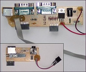 To keep the track complexity down on the mainboards, I routed all signals off to header pins and made seperate boards for the real external connectors. These boards are pretty simple: I used mini DIN sockets for the video out (8 pin) and serial port (4 pin). The joysticks are standard Atari 2600 D-plugs which nfortunately is the same connector and gender as used on PCs for the serial COM ports but I dont think anyone is going to mix them up :)
For simplicity the audio/video connector board (inset) has a latching multipole mechanical push switch that allows selection of external video or the laptop’s own LCD. The sound output is also switched mechanically using the switch-over contacts of the serial jack socket.
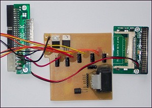 The larger PCB has the serial port socket, dual joystick ports (a diode OR with select line allows simple multiplexing of the same 6 control signals) and on the right is the DC power jack. This connects to the 3Amp 7.5V adapter that came with the PSone LCD – handy, that. As the FPGAs prefer a smooth power up, I made a “soft-power” system using a SMD PIC and power MOSFET – the output goes directly to to the LCD and the various voltage regulators (5V, 3.3V, 2.5V) for use throughout the system. (The regulators are linear types but as the drop out is quite small, they dont get particularly hot.)
The lower picture shows the main power board (most of the regulators are SMD types on the solder side underneath). There’s also an (experimental) MMC connector made from an old PC floppy drive connector. The two green boards left and right are off-the-shelf IDE adapters, the left is for 3.5″ to 2.5″ drive and the right is for 3.5″ to Compact Flash. Naturally it’d be more elegant to get the actual connectors and make an all-in-one PCB but at the time I couldn’t find them available and I had these adapters spare.
Building a case
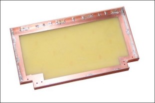 I made most of the structure from copper-clad board (the stuff normally used for PCBs) as it’s rigid, easy to cut and solder together. Originally, I suspected I’d need to use brass angle along the seams but it turned out that a good run of solder alone is strong enough – just need to make sure the angles stay true. I etched off the bulk of the copper to reduce the weight – it didn’t make that much difference however (less than 10%). A little epoxy filler was used to fill in the gaps and the whole thing was sprayed with primer and black paint. In some places I used 2mm plasticard (HIPS) and polystyrene cement but I kept this to a minimum for several reasons. 1. The glued seams were noticable even after spraying, 2. The spray paint peeled away from the plastic easily – even after keying with Scotchbrite pads and using primer.. 3. The plastic charges up with static electricity readily – obviously not particularly desirable.
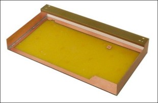 The dimensions of the case were mainly determined by the keyboard. I used a compact laptop style keyboard which I’d bought off ebay a while ago (approx 29 x 14 cm). Its original housing was removed and adapted to suit and some of the “quick function” buttons were desoldered to make way for a small PCB with my power/reset/NMI buttons and status LEDs. (Aside: I had implemented the PS2 protocol on the mainboard for communicating with a standard PC keyboard, but of course when I took the mini-keyboard apart I had direct access to the key matrix. I could’ve therefore made a custom key scanning system if I’d wanted).
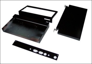 The PSone LCD display which I was using has the controller board mounted behind the TFT module, meaning a thickness of at least 1.5cm for the laptop’s lid. Internally it was just a matter of creating some mounting pillars for the TFT and PCB and making sure the holes for the brightness/volume buttons were in the right place. The speakers from the original PSone unit were used without much modification – some pieces of spare speaker grill were cut to size, slightly bevelled and glued into the rectangular holes I’d cut (some thin bezels hid the edges on the outside).
OS etc
I’ve been developing my own operating system throughout the course of the Z80 project and I was able to use pretty much the same code for Version 4. It takes the form of a command line interface, the kind you might find on a freezer cartridge from back in the day (Action Replay et al). Most of the usual DOS commands are there and there’s a memory monitor / disassembler etc. Executables can be run by entering their filenames as a command. On power up, the OS loads from the first few sectors of the HDD if found (if not you’re prompted to download some code via the serial port.)
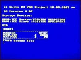 With this version some improvements were made.. For a start I’m no longer fixed by hardware to a 32×24 character display so the editor window has been made more flexible. The main improvement has been in the storage dept though.. Originally I/O was fixed to the IDE port allowing master and slave drives called IDE0: and IDE1: but now drive names are more virtual and are assigned to devices (“DRV0:”, “DRV1:” etc) as they are found upon boot (or when manually mounted). Each device has its own Get_ID, Read_Sector, Write_Sector routine, and these are called as appropriate for the currently selected device. This way, any storage device that allows access via 512 byte sectors can accepted by the operating / file system (with an appropriately written driver of course). I also changed the primative serial IO protocol to sends files in packets with a checksum at the end of each. This way, any error is detected almost immediately instead of waiting for the whole file to be sent and then issuing an error.
Demo!
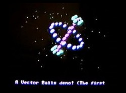
Here’s a clip of a graphics demo I coded. The V4 graphics engine can display 56 256-colour sprites without any multiplexing so a I thought a simple vector ball demo would be an ideal test. (Ah, 8 bit maths and a CPU with no multiply instructions, good old look-up tables:) It runs at full PAL frame rate (of course!) but the capture process has reduced that to 25fps on the clips available here…


